
Self-contained CRT Clocks
|
3GP1 CRT based Clock |
5UP1 CRT based Clock |
I built these CRT clocks using a board developed by Jon Stanley (Electronixandmore) and myself. This board contains electronics to generate the high voltages, necessary for old fashioned CRTs like the 3" 3GP1 and the 5" 5UP1 used in these clocks, to amplify (push-pull) the X-Y voltages suitable for the CRT deflection plates and a complete Dutchtronix AVR Oscilloscope clock. The board also has footprints for a simple oscilloscope section and a simple TV section. These last 2 sections are not used and therefore not populated, though the parts can be added later, if desired.
Jon wrote a very detailed Operators and Service Manual for his design. It is recommended reading.
A newer CRT driver board without the built-in scopeclock is available from Catahoulatech.
Both designs use a Hammond 271X transformer to supply the required AC voltages: 280-0-280, 5v, 6.3V. In this design, the 5V AC winding is used to power the CRT filament, the 6.3V AC winding is used to generate +5V and -5V stabilized voltages. The 280-0-280 AC winding is sent to a rectifier/doubler section to generate the following voltages:
| G1 | -780V |
| K | -750V |
| A1 | -580V |
| A1 | +180V |
| +HV | +400V |
The 280-0-280 AC voltage is actually reduced a little using 2 power resisters to make sure the +HV line does not exceed 400V. This is important since the ZTX458 transistors used in the amplifier section are only rated up to 400V.
The 6.3V AC winding is also used to generate a 60Hz signal which the AVR microcontroller uses to maintain time. This is different from the Dutchtronix AVR Oscilloscope Clock which uses a signal from the PCF8563 Real Time Clock to advance the clock 1 second. In this CRT Clock design, the PCF8563 is only used to maintain time when the CRT Clock is turned off.
The 3GP1 based CRT clock is equipped with a CRT shield which allows it to operate fairly close to the Hammond 271X power transformer without interference from the transformer's magnetic field. This results in a nice, compact design using an acrylic case with a nice, sharp and stable image.
Unfortunately, I did not have a suitable CRT shield for the much larger 5UP1 CRT and therefore had to mount the transformer away from the CRT. The 5UP1 CRT based clock is therefore significantly larger. It uses a aluminum frame with a acrylic plate to mount the CRT.
Note that some CRT Clock designs synchronize their screen refreshes to the net frequency to minimize such interference. Since the Dutchtronix AVR Oscilloscope clock has refresh rates in the order of 150 to 200 Hz (dependent on the selected clock face), this would involve a very significant refresh rate reduction, resulting in lots of screen flicker, I decided to maintain the high refresh rate and use the screening/distance method to deal with the transformer's magnetic field.
The 5" CRTs like the 5UP1 require higher voltages to operate than those required by a 3" CRT like the 3GP1. The voltages that the board generate are barely enough; they do generate a clearly visible image but the image is not as sharp and stable. Older CRTs suitable for projects like these are difficult to find so sometimes we have to make compromises.
Both clocks are controlled by a single push button which is conveniently located on the front. The image adjustment trimmers (ASTIG, INTENSITY and FOCUS) are on the PCB. Though the High Voltage (HV) points on the PCB are shielded, extreme caution is advised when setting these trimmers. Touching an HV point stings and will cause you to retract your arm in an uncontrolled way, potentially damaging the CRT. The image adjustment trimmers (XSIZE, XPOS, YSIZE, YPOS) are also on the PCB but they are not close to an HV point.
Like all Dutchtronix AVR Oscilloscope Clocks, these clocks are equipped with a serial port, which can be used to control the clock or hook these clocks up to a GPS unit, to make sure they show accurate time. The serial port connector provides TXD, RXD, GND and +5V. TXD and RXD operate to TTL levels. Interfacing to a PC therefore requires an RS232 level converter.
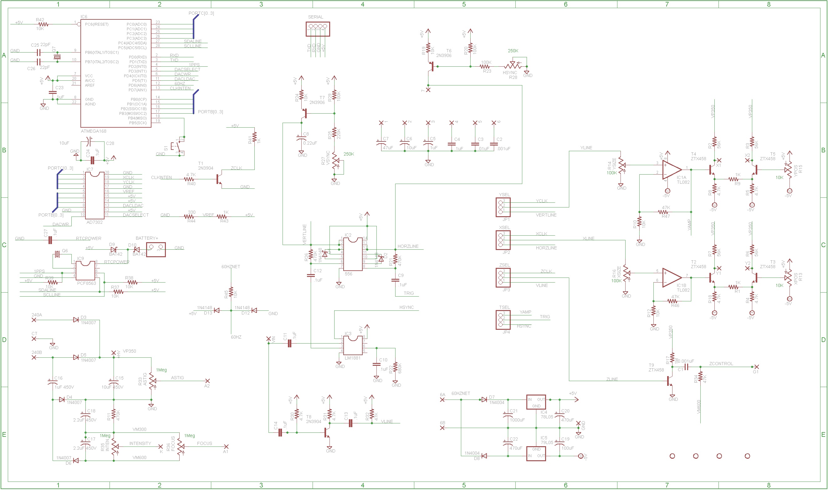
Here are the Schematics:
Here is what the result looks like:
3GP1 based CRT Clock
.JPG)
3GP1 based CRT Clock
.JPG)
5UP1 based CRT Clock
.JPG)
For suggestions and corrections, please contact me at:
![]()
![]()
![]()
![]()
.JPG)

.JPG)