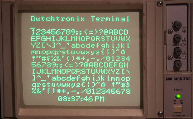
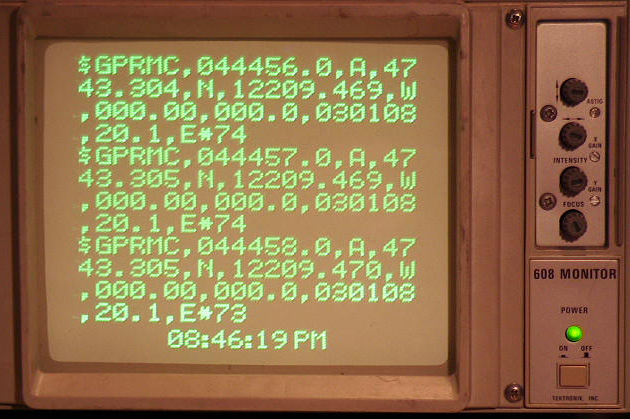
Startup screen Displaying NMEA output
If you ever experiment with microcontrollers, you know you need a way to get status information from your microcontroller and you don't want to use a lot of precious pins to do that.
Serial devices are by far the easiest way to do this since most microcontrollers (at least AVRs) have a serial device built-in. Simple code is minimal and you only need to sacrifice 1 pin to be able to send output.
The problem with a plain serial port is that you need a terminal device, usually a computer, but the computer isn't always conveniently located near the work bench.
LCD displays are very nice but require quite a few pins and added code. Some people buy or build a serializer board for their LCD display, including its own microcontroller to provide an effective display device.
A device that frequently is located on your workbench, but mostly doing nothing, is an oscilloscope. Maybe you got yourself a Dutchtronix AVR Oscilloscope Clock to make it more interesting, possibly to keep an eye on the time. What if you could use that oscilloscope as a display device for your microcontroller projects?
Enter the Dutchtronix AVR Oscilloscope Terminal:
|
13 lines, 20 characters per line | |
|
Displays full ASCII character set including upper and lower case | |
|
Automatic superfast scrolling | |
|
Flashing cursor | |
|
Delayed CR/LF control | |
|
Current time is displayed and updated at the bottom of the screen | |
|
Separate command mode to configure the AVR Terminal (short push on push button switch) | |
|
Multiple Baud Rate support. Current Baud Rate saved in EEProm | |
|
AVR Assembly Source Code so you can customize the terminal |
This terminal is an application running on the Dutchtronix AVR Oscilloscope Clock, Hardware 2.0. All you need is a serial cable as described here and a PC to reprogram the AVR Clock and it will turn into an AVR Terminal. This application is provided to you free of charge so if you already have the Dutchtronix AVR Oscilloscope Clock, you now also have the Dutchtronix AVR Oscilloscope Terminal. Reprogramming the AVR to switch between these two applications is easy!
Connecting the AVR Terminal to a PC running a terminal program is done using the same serial cable as used for programming and talking to the AVR Clock. Using this setup, you can configure the AVR Terminal and try it out, for example by using your terminal program to send a large text file to the AVR terminal. You'll notice the incredible scrolling speed, without losing a single char.
Connecting the AVR Terminal to a device that sends out text over its serial port is much more useful, but it can also be frustrating to get going because of 2 issues:
|
Serial Communication can electrically be done in at least 2
ways: |
|
Serial communications is based on a TX line and an RX line.
You need to make sure that the TX line of the sending device is connected to
the RX line on the AVR Terminal (pin 3 of the serial port connector). The serial cable to communicate with a
standard PC will probably not work! Making a second serial cable is by far
the easiest solution; that way you can switch cables to talk to a PC or to a
microcontroller circuit. An alternative is to connect a "NULL MODEM" cable
to your existing cable to switch the RX and TX lines. Make sure you pay
attention to the DB-9 connectors used on your cabling: there are male ones
and female ones. | |
|
The Dutchtronix AVR Oscilloscope Clock Hardware 2.0 uses a parasitic level shifter (using transistors, diodes and resistors). This is a cost and space effective solution but it limits the maximum baudrate to 57,600 baud. This limitation disappears if you bypass the level shifter as described above. |
Once you have conquered these issues, you're in business. Good luck and enjoy!
Operating Instructions:
The AVR Terminal starts up at 19,200 baud in "Terminal mode". It will display every incoming character within the full 7-bit ascii range. The following non-displayable characters are interpreted: BS (08), HT (09), LF (10), CR (13). Other non-displayable characters like ETX (decimal 3) are displayed using the ^ character, in this case "^C". Look here for an overview of the ASCII character set.
To change to "Command Mode", push the on board push button switch once (short push). You now can communicate with the AVR Terminal using a terminal connected to the serial port, just like the Dutchtronix AVR Oscilloscope Clock. Use the 'X' key to get a prompt. The available commands are:
|
T for set Time. The AVR Terminal will ask you to enter the new time. | |
|
B for switch Baudrate. This allows you to switch between 19,200 baud and 4800 baud. Please immediately change the baudrate of the terminal you are using following the command confirmation. The new baud rate will be saved in EEProm location E2END-2, which does not interfere with the Dutchtronix AVR Oscilloscope Clock use. |
Use another 'X' to cancel the prompt. The prompt will time-out after 30 seconds. Command letters are case insensitive. Push the button switch again (short push) to go back to "Terminal Mode".
The AVR Terminal will display a blinking cursor at the current position about 1 second after receiving the last incoming character. This delay prevents a lot of useless setup when a burst of character is being received.
The AVR Terminal uses a delayed Linefeed
mechanism to process control characters. The reason for this is that you don't
want to advance to the next empty line (and possibly scroll the display) until
an actual character is ready for that next line. A Linefeed (LF) character
advanced to a new line but only when a character for that new line is received.
Normally, the blinking cursor indicates the location where the next incoming
character will be displayed. However, if a LF is pending, the cursor will be on
the last character of the current line (or when the line is full since this
implies a LF).
The CR character followed by a printable char is interpreted as a Carriage
Return, meaning the cursor goes back to the beginning of the line (without
blanking the line), so that you can potentially update the same line with status
information by repeatedly sending a status line, followed by a CR. A CR
character followed by an LF character is treated as just an LF character. Where
two or more CR characters in a row are received, all but the first one are
interpreted as LF characters. To advance to the next line, please use an LF
character, or 2 CR characters.
When using a terminal program like HyperTerminal or Bray's Terminal to send lines of text to the AVR Terminal, please select the option to include a LF with the CR character; both programs provide this option.
The character display you see in this Dutchtronix AVR Terminal is also used in the V3.0 firmware update for the Dutchtronix AVR Oscilloscope Clock, which uses a similar character display mechanism.
For more information, email me at:
![]()
About Display Quality
Using a microcontroller to drive an Oscilloscope as a display device is somewhat of a compromise. The oscilloscope beam needs to move all the time to provide an even picture. When the AVR gets very busy, for example when it is receiving a massive amount of text, you will notice a bright spot at the lower right corner of the time display. This is caused by the fact that the AVR is processing a large block of incoming characters (in between screen refreshes) and cannot move the beam while doing that. When the screen is empty, the clock display line becomes quite bright, because the AVR does nothing but display the clock line. In other words, the refresh rate is going up. The intensity control provided on the Dutchtronix AVR Oscilloscope Clock board (marked 'Z') is quite effective at suppressing the bright dot.
AVR Oscilloscope Terminal 3.0a Firmware Image (19-Feb-2008)
AVR Oscilloscope Terminal Source Code (19-Feb-2008)