Sections:
|
Introduction | |
Dutchtronix AVR Oscilloscope Clock Hardware 2.0 FAQ
Firmware Version 3.0
January 31, 2008
|
Sections: |
|||||||||||||||||||||||
|
|
Introduction.
Dutchtronix is proud to present a new firmware version for the Dutchtronix AVR Oscilloscope Clock, version 3.0. Many new features were added and bugs were fixed (did you know you could not set the year in the previous versions to 2099?)
If you have an older firmware version loaded in your AVR clock and made an AVR Clock serial cable (or are willing to make one), give this update a try. You can test the serial cable for proper operation by trying the Command Line Interface first. Remember, it is always possible to restore the AVR Clock to firmware V2.7a or earlier (see archives).
One major challenge in the development of the V3 firmware for the AVR Oscilloscope Clock was to rewrite the existing software to reduce its size enough to make room for all the new features. One of these rewrites produced a completely new Character Generation method. This method is very space efficient and supports the display of all printable ASCII characters. A positive side effect is that there are fewer highlighted dots visible within the characters. For those interested in the technology, the same method is used in the Open Source Application available for this AVR Oscilloscope Clock board: the Dutchtronix AVR Oscilloscope Terminal. Download the source code for either the AVR Oscilloscope Clock or the AVR Oscilloscope Terminal and take a look.
Image quality varies from scope to scope of course. X-Y monitors, which are like oscilloscopes but without the time-base section, work best. All pictures showing the new V3 firmware were taken on a Tektronix 608 X-Y monitor using the Intensity Control output ('Z') available on the board.
New Features in V3.0:
|
Binary Clock Display option (Menu-Dial:Bin). This is a BCD binary clock. Show them you are an ubergeek! Try changing the current time when the Numeric Display is turned off! | |
|
24 Hour Clock Dial option (Menu-Dial:24hr).To see the exact time on an analog dial, when no numeric date is being shown (for example when the current date is displayed or when the Numeric Display has been turned off), you need a dial showing the 24-hour time digits. The dial will switch automatically, based on the current time. | |
|
More into a classical clock dial? Use Roman Numerals Dial option (Menu-Dial:Rom) | |
|
Date Display is now supported (Menu-Num:Date). The date can be changed using a long push while the date is being displayed in the Numeric Display. | |
|
Hexadecimal Numeric Time Display (Menu-Num:Hex). This option was designed to work together with the Binary Clock Display to form a "Bi-Hex" clock. | |
|
Fractional Seconds Display option (Menu-Chrono:On). This mode will add a display of 1/100 of a second unit to either the 24 hour Numeric Display or the Hexadecimal Numeric Display | |
|
The AVR Oscilloscope Clock now supports a total of 30 different display combinations. | |
|
GPS device NMEA parsing ($GPRMC records) allows you to connect your GPS device to the AVR Oscilloscope Clock and always display the correct Date and Time. You select the correct Local Time Offset (-12 to +12) when enabling this option in the Menu. If Automatic Daylight Saving Time Adjustment is enabled (see below), you don't have to worry about that either. | |
|
Automatic Daylight Saving Time Adjustment is supported for two zones: USA and EU for the years 2008 to 2014. Not only will the AVR Oscilloscope Clock set the time forward or backwards at a transition, it will also apply the proper adjustment when the clock has been turned off for a while and is turned on when Daylight Saving Time is active, and it will only do it once. Keep in mind that the Real Time Clock present on the AVR Oscilloscope Clock knows nothing about Daylight Saving Time. | |
|
User Name Display on the clock face is now supported. This User Name can be up to 20 characters in length. By default the name "Dutchtronix" is displayed (or the name of your distributor) but you can edit the User Name in the menu (granted, it is a slow process but it only needs to be done once). Spaces can be used in the User Name, but 2 adjacent spaces indicate the end of the User Name. You can also turn off the User Name Display. | |
|
Need to return the clock to its original state? Select the Menu-Reset:On option. This will clear the EEProm configuration data. Handy if the EEProm configuration data ever get messed up. This option requires an explicit ON value to prevent the user from accidentally erasing the EEProm configuration data. | |
|
The previous Menu options SPEED:NORM or FAST and DIR:NORM or REV have been combined in the Play option: Menu-Play:Norm/Rev/FF/FR where FF means Fast Forward and FR means Fast Reverse. | |
|
The Serial Command Line interface has been updated; some commands now require sub-values. For example to set the Numeric Display to show the date, enter "xn", followed by "03". The clock will prompt for the sub-values, showing the valid range. | |
|
The RTC CLOCK MASTER mode from previous firmware versions has been removed. The AVR is now always the clock master, reading the current time/date from the Real Time Clock (RTC) when starting up. The current time is saved to the RTC every minute. The RTC date is updated whenever the date is changed (user or GPS input). | |
|
The demo mode available in the AVR Clock has been updated to show many of the new V3 features. | |
|
The on-screen menu has now 13 fields and going through them all without making a change takes 13 long pushes. If you enter the menu by accident, just advance to the "Boot" field and do a short push; the clock will restart instantly. | |
|
The bootstrap loader was improved so that proper AVR signature data are now returned, which allows the use of download programs other than AVRPROG.EXE. The Open Source Application AVROSPII.EXE now works as well. Since the bootstrap loader is permanently present in the Atmega168 microcontroller, these improvements are only available in AVR clocks originally shipped with firmware V3.0 or later. |
Q: What kind of oscilloscope can I use?
A: Any analog scope with X-Y mode should work without problems. Low-end digital scopes will surely not work, High-end digital scopes may work (Tektronix 2014B works ok, HP54600B works well) . High-end analog scopes (400 MHz or better) like the Tektronix 7904 or 7854 will not have as stable a picture because their phosphor decay time is so short; this will make the picture look less stable, even at a refresh rate of over 150 times a second. On scopes like the Tektronix 465 and 475, the picture is rock solid. Please let me know if you’ve been successful with a digital scope.
Q: What kind of cables should I use to connect the clock to the oscilloscope?
A: The easiest way to connect the AVR clock to your scope is to use two 10X
probes with pincer tips. The CH1 and CH2 terminals were selected to be easily
useable for probes with pincer tips. Because of the very high output impedance
of the TLC7528 DAC, there will be some high frequency noise, which can be
minimized by engaging the BW limit option on the oscilloscope.
Using 1X probes (or BNC cables) is not recommended since their capacitance loads
the signal down to the point at which the retrace vectors are visible. This
effect can be minimized by adding load resistors. Connecting the scope’s intensity control to the Z output of the AVR
clock will also help.
Connect the 10X probes to the terminals marked 1 and 2. Set the scope in X-Y mode
and connect the probes to channels 1 and 2. Set both channels to DC mode and the
voltage range to 0.5V per division. You can tweak the display size by using 0.2V
per division and manually reducing the voltage per division value (VAR knob.)
Most scopes define CH1 and the
X axis and CH2 as the Y axis. Some, for example the Tektronix 485, reverse this
convention. As a result, you will need to swap the probes.
Q: How do I power the AVR clock?
A: The clock requires 5V regulated power on the 2 prong adapter, + and - are marked, though somewhat obscured by the header. The +(positive) is on the side of the RS232 header, the –(negative) is next to the Real Time Clock (RTC) crystal. The –(negative) side is marked as a ‘1’ on the connector itself, though the marking is very small. You can make a cable using the supplied 2-pin connector. This connector is polarized so reversing the power when you using this connector is not possible (provided the cable is made correctly).
Q: Where do I get a 5V regulated supply for the AVR clock?
A: There are many ways to obtain a 5V supply. The easiest is to use a "bench supply", a device used by many electronics hobbyists to power their circuits.
Another way is to build a very small circuit using a 7805 or 78L05 regulator. This circuit takes power from a 7-12V wallwart (a small transformer with a rectifier that plugs directly in an outlet an produces an unregulated voltage of 7-12V. Unregulated means that the voltage changes when the current being used changes. The job of the 78(L)05 regulator is to stabilize this voltage at 5V, irrespective of the current use.
Another option is to sacrifice a USB cable, cutting of the non-computer side connector. The red wire is +5V, the black wire is ground. You can attach the crimp connectors directly to these wires and insert them into the terminal housing (both are supplied with the AVR clock). The drawback of this solution is that you need a computer close by.
Q: Do I need to make the AVR Clock Serial cable?
A: No, use of the Serial Interface is optional as of firmware version 2.6. The Dutchtronix AVR oscilloscope scope clock now uses the on-board button switch to set the time and has an on-screen menu to set options, using the same switch.
|
Q: How is the on-board
button switch operated?
Menu mode:
|
|
Q: How do I change the time on the AVR Clock using the button switch?
A: To change the time, make sure that the Numeric Display does NOT show the current date. If so, change it using the menu. A long push will enter the Change mode. If the Numeric Display is Off, the time will also be changed, even if the Binary Clock Display is active. The clock is stopped when changing time. The value being changed will flash at this point. If the Numeric Display is Off, one of the Clock Hands will flash in an Analog Dial Display. In a Binary Clock Display, the "lights" columns representing the value being changed will flash. A short push will increment the current field (hours, minutes, seconds). A long push will move to the next field, using the current field value as the new time value. Once done with the seconds field, a "Push To Start" message pops up. A short push will restart the clock at the selected time. However a long push will restart the clock at the actual time, as kept by the on-board Real Time Clock. This is handy if you entered the Change mode by accident or if you changed your mind. Change mode times out after 30 seconds of inactivity.
Q: How do I change the date on the AVR Clock using the button switch?
A: To change the Date, make sure that the Numeric Display shows the current date. If not, change it to display the Date using the menu (Menu-Num:Date). A long push will enter the Change mode. The value being changed will flash. A short push will increment the current field (year, month, day). A long push will move to the next field. The clock leaves Change mode automatically after finishing the Day value. The order of change is Year, Month, Day. This way, the clock can verify the date validity better (number of days per month, leap year etc.) Just FYI, 2000 is a leap year in the Gregorian Calendar because it is divisible by both 100 and 400. Change mode times out after 30 seconds of inactivity.
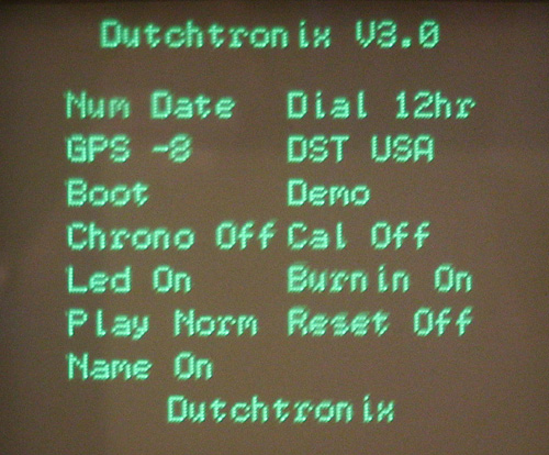
Q: What options are available
using the on-screen menu?
A: A short push will enter the Menu
Mode. Once the Menu mode is entered, you'll see the following menu on the
oscilloscope screen:
|
Option |
Values |
Function |
Option |
Value |
Function |
|
Num |
12hr |
Select Numeric Field to Display |
Dial |
12hr |
Select Clock Dial to Display |
|
GPS |
Off |
Select GPS NMEA input using the selected local time zone offset |
DST |
USA |
Select Automatic |
|
Boot |
Reboots the clock |
Demo |
enter DEMO mode |
||
|
Chrono |
Off |
fractional seconds |
Cal |
Off |
Turn Calibration Screen On or Off |
|
Led |
On |
Controls on-board Led |
BurnIn |
On |
Turn Burn-in Prevention On or Off |
|
Play |
Off |
Fun modes: Reverse, Fast Forward and Fast Reverse |
Reset |
Off |
Re-initialize the EEProm area of the Atmega168 to "virgin" state. |
|
Name |
On
|
User Name Display |
Current User Name is displayed below the Menu |
Q: How do I change an option
on the AVR Clock using the button switch?
A: A short push will enter the Menu Mode. The option being updated/selected is
flashing. Move to the next option by a long push. The options Boot
and Demo are
activation options. A short push will activate them. The other options are
selection values. A short push will show the next selection value. Moving to the next option
(using a long push) when the selection value has changed, will activate the
selected value
and the clock will leave the menu mode. The Boot
option is also a convenient way to exit the menu. Menu mode times out
after 30 seconds of inactivity.
Q: How do I tell the AVR clock to display only the analog clock?
A: Select the Num option, set the value to Off. This mode is persistent.
Q: How do I tell the AVR clock to display a minimal dial on the analog clock?
A: Select the Dial option, set the value to Min. Only 4 hour numbers will be displayed. This mode is persistent.
Q: How do I tell the AVR clock to display a dial with Roman Numerals on the analog clock?
A: Select the Dial option, set the value to Rom. Roman Numerals will be now be displayed on the dial. This mode is persistent.
Q: How do I tell the AVR clock to show a Binary Clock Display ?
A: Select the Menu-Dial option, set the value to Bin. The clock will switch to a Binary Clock Display. This clock will display 24 Hour time in a BCD Binary fashion. You will see 6 columns displaying from 2 to 4 on-off "lights". The left-most 2 columns show the hours, the middle 2 columns show the minutes and the right-most columns show the seconds. Each column represents one digit, together they form a value. The lowest position in each columns represents bit 0, the highest can be bit 2, 3 or 4. The size of each column was selected to represent the full range for each digit in its position. For example, the lowest digits for seconds can range from 0..9 so we need 4 bits to display the number 9 in binary. The highest digit for hours can range from 0..2 so we only need 2 bits to display the number 2 in binary. When you select a hexadecimal Numeric Display (Menu-Num: Hex) with this Binary Clock Display, you are looking at a Bi-Hex clock. This mode is persistent.
Q: How do I read the Numeric Time in Hex?
A: The Numeric Time in Hex is a binary representation of the values of the time components, in 24 hr format. Convert each field from hexadecimal to decimal (0..59) and you'll see the current time. There is no separate BCD Hex Numeric Display since such a display is identical to the regular 24 hr Numeric Display since each digit is in the range 0..9 (identical in decimal and hex)
Q: How do I tell the AVR clock to display the Numeric Display in AM/PM mode?
A: Select the Num option, set the value to
12hr. This mode is persistent.
Q: How do I change the Clock Face to something more serene?
A: The AVR clock provides 3 different controls to change the clock face, providing a total of 30 different combinations. Use the Num option to turn the numeric display Off . Use the Menu-Dial:Min option to remove most digits from the clock face. The combination of no numeric display and fewer digits provides a minimal but elegant display. You can select the Numeric Display format with the Num option, value 12hr, 24hr, Hex, Date, or Off
Q: How do I change the User Name to my own preference?
A: The current User Name is displayed at the bottom off the menu page, but is not a normally selectable field. You must explicitly select the "Edit" option in the "Name" field to change the User Name. The reason for this is that editing is cumbersome with just one push button. Once a User Name edit has started, you have to go all the way to the end of the name, followed by 2 spaces, to complete the edit. Therefore an explicit selection is required.
If you are impatient like I am, you may produce several expletives when entering
your desired name since you just pushed the button one too many times, and ended
up with the next letter. Luckily, you only have to enter the desired User Name
once only since the name is stored in the AVR EEprom. Flashing may obscure the current
char for a very short time (1/2 second) so be patient when incrementing a
letter: if you go to far, you'll need to push 96 times to get back to where you
were!
The actual edit process is simple: the character being changed flashes. A
short push "increases" the char in an ASCII sequence (ASCII 127 is the highest
char available, after which rotation to SPACE (ascii 32) occurs.
A long push advances to the next char in the name. Spaces are allowed, but only
one at a time since a sequence of 2 spaces is interpreted as the end of the User
Name (a full buffer also ends editing). If you entered the edit mode by
accident, you can either advance to the end of the name by using long pushes,
followed by 2 spaces, or you can just wait 30 seconds and the clock will
time-out the edit mode.
Display of the User Name can be turned off using the "Off" option the "Name" field.
Q: What happens when I change the User Name to an empty string (0 length)?
A: The Dutchtronix AVR clock V3.3 or up will write an User Name with one space to the EEprom area. Versions before 3.3 will write incorrect information to the EEprom area so please avoid 0 length User Names.
Q: What is the "Automatic Daylight Saving Time" feature all about?
A: Daylight Saving Time, called "Summertime" in the European Union, is a time system where time is advanced by one hour sometime early in the year and time is set back one hour near the end of the year (in the Northern Hemisphere.) When you live in the USA or Western Europe, you won't have to change the clock to correct for Daylight Saving Time (DST) until 2015! The dates when DST takes effect and ends are programmed in the AVR clock for the years 2008-2014, based on the most recent laws, both for the USA and the European Union.
Not only will the clock automatically set the time one hour forward (and one hour back) when transitioning in and out of a DST window (the combination of date and time for which DST is active), the clock will also set itself to the proper time if it has been turned off for a while. Even though the Real Time Clock (RTC) on the AVR clock keeps running when the clock is turned off, it is not aware of DST so the RTC time will be off by one hour if it was turned off before a DST window, then turned on within such a window. The AVR clocks make the necessary adjustment when turned on. The clock keeps track of the adjustments made for each of the 7 supported years so that adjustments (forward and backward) are only applied once.
If the user manually changes the date, the clock will check if this new date requires a DST adjustment and will do so, if needed.
If the user manually changes the time, the clock assumes the user knows best, will not do an DST adjustment but will mark that a DST adjustment was made for the current year (if appropriate).
The time at which DST starts and ends is fixed at 2:00 AM. This is valid for the USA and most of Western Europe. However in the United Kingdom (which has UTC time), DST starts and ends at 1:00AM. There is no separate UK zone so the AVR clock is not 100% accurate for those living in the United Kingdom.
The automatic DST feature also works with the GPS NMEA input mode, again assuring you of an accurate date and time. Combine GPS NMEA input mode with Automatic Daylight Saving Time and you'll have the correct date and time until March 8, 2015, 01:59 AM, accurate to within 10 milliseconds (when also using the GPS 1 PPS input.)
Q: What does the "Chrono" Menu option do?
A: The Chrono option in the menu enables a fractional seconds display in the 24 hrs and hexadecimal numeric display modes. This fractional seconds display shows the current time in 1/100 of a second increments.
Q: Why does the clock display jump ever so slightly every 5 minutes?
A: The AVR clock offsets the display slightly every 5 minutes to prevent screen burn-in on your oscilloscope. You can toggle this burn-in prevention feature on or off using the BurnIn option, value On or Off. This mode is persistent.
Q: Why doesn’t the Calibration Screen change location to prevent Burn-in?
A: This is a design decision. Having the Calibration Screen move while you are aligning the screen doesn’t seem to be a good idea. Keep in mind when aligning that the actual screen will move by a very small amount every 5 minutes unless burn-in prevention is turned off
Q: What does “this mode is persistent” mean?
A: It means that the mode is remembered when the power is turned off, and the clock will start in the same mode when the power is turned back on. This is achieved by setting status bits in the EEProm section of the Atmega168.
Q: How do I align the clock properly on my scope?
A: Select the Cal option, set the value to On , which will display a Calibration Pattern on the scope, to adjust the display. While in Calibration Mode, use the Volts/Div VAR knobs together with the position knobs to get the best square possible; this screen can also be used to fine-tune the probe compensation adjustments. Get back in the Menu mode (short push), Select the Cal option, set the value to Off , to return to the normal clock display.
Q: How do I tell the AVR clock to start and stop blinking the LED?
A: Select the Led option, set the value to On or Off to toggle the LED blinking. Stopping the blinking LED will also suppress the valid NMEA record received notification on the display ('G') if GPS mode is enabled. This mode is persistent.
Q: How do I reset the AVR clock without disconnecting power?
A: A short push on the button switch on the AVR clock enters the Menu mode, advance to the Boot field (it will be flashing when it is selected). Another short push will active the Boot option, causing a system reset, initiated by the AVR. Shorting pins 5 (Reset, active low) and 6 (GND) of the ISP connector will hardware reset the AVR clock. Normally, no connector is present on your board, but you can solder in a 2-pin header. There are 5 columns of 2 pins each; use the middle column.
Q: Is there another way to communicate with the AVR Clock?
A: Yes, you can also use the serial interface to communicate with the AVR Clock. This requires an AVR Clock serial cable and a terminal, usually a terminal program on a PC. Use the letter "x" to obtain a prompt. This interface is completely optional.
Q: How do I know which version of the firmware my clock is running?
A: Enter menu mode using a short push. The top line shows the current firmware version. On versions before 2.6, there is no menu (a short push will reboot the clock). The serial connection will also display the firmware version, both when starting up and when using the status command ("s").
Using an External Clock Source
Q: How do I apply an external
clock source to the AVR clock?
A: The AVR clock normally receives a 1 PPS
(Pulse per Second) signal from the RTC and triggers on the negative going edge.
This pulse can be intercepted and replaced at JP6. The JP6 pins are normally
shorted by a shorting block, but you can feed your own 1 PPS signal to the pin
closest to the AVR microcontroller.
Q: How do I hook up the AVR Clock to my GPS unit?
A: Connecting your GPS unit to the AVR Clock is simple once you get the correct cabling. This step may be frustrating though.
|
Serial Communication can electrically be done in at least 2
ways: |
|
Serial communications is based on a TX line and an RX line. You need to make sure that the TX line of the GPS unit is connected to the RX line on the AVR Clock (pin 3 of the serial port connector). The AVR Clock serial cable used to communicate with a standard PC will not work! Making a second serial cable is by far the easiest solution; that way you can switch cables to talk to a PC or to your GPS unit. An alternative is to connect a cross-over cable to your existing cable to switch the RX and TX lines. Make sure you pay attention to the DB-9 connectors used on your cabling: there are male ones and female ones. Combining a "gender changer" and a cross-over cable is a good option. |
You can use the Dutchtronix AVR Oscilloscope Terminal application to test out the serial communication between a GPS device and the AVR oscilloscope hardware! Once the connection is working, configure the GPS unit to send out NMEA $GPRMC records at 4800bps; this is the default on most units.
The GPS device may send out lots of NMEA information every second.
The AVR clock will have to process every record, discarding most of them.
Even though the Serial Input on the AVR Clock is completely
interrupt driven and buffered, it does take some time to find the
individual NMEA records, time during which the oscilloscope screen
cannot be refreshed and you will see an intensified dot on the screen when a lot
of unwanted NMEA records are streamed by the GPS unit. If you can, disable the sending of other records and set the send
frequency of the $GPRMC record to no more than once every 5
seconds; this is not required but makes it easier for the AVR Oscilloscope Clock. If
necessary, also select UTC time, not GPS time. Do not connect
the cable to the AVR Clock yet at this point.
Start the menu on the AVR Clock and advance to the "GPS" field. The
default value is "Off". Short pushes will cycle you through the possible
options. These numbers indicate your "local time zone offset" from UTC
(Greenwich time). For example, the local time zone offset here in the Northwest
is -8. For the United Kingdom, the offset is 0. Activate the selected option and
connect the cable. If all is well, you will see the letter 'G' appear in the
status field every 4 to 5 seconds, lasting 1 second. This indicates that the AVR
clock has found a valid $GPRMC record. The 4 to 5 seconds is because the AVR
clock will wait 4 seconds after finding a valid $GPRMC record before accepting
another one. Parsing these records costs time, including several ASCII to binary
conversions, so the AVR Clock waits 4
seconds after receiving a valid record. If the AVR clock determines that its time and/or date differs from the
time and/or from the GPS device (after adjustments for the local time zone
offset and possibly Daylight Saving Time), it will update itself and start a 5 second
warning (flashing 'G'). This should be very infrequent. The display of a 'G'
every time the AVR Clock receives a valid $GPRMC record can be turned off using
the Menu-Led:Off option.
Please remove the GPS cable before changing the "GPS" field in the AVR Clock menu to "Off". First of all the baud rate of the serial port is changed from 4800bps to 19200 bps and secondly, the AVR clock will try to interpret the incoming data (from the GPS device) as commands.
Combining the 1PPS signal from a GPS unit with NMEA parsing will give you an extremely accurate clock which will continue running even if you lose the GPS satellite signal (displaying the 'P' warning); the clock will correct itself, if necessary, once another lock is obtained.
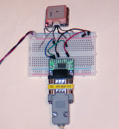
SparkFun Electronics kindly made one of their current GPS units, the amazing EM406a Sirf III from USGlobalSat, available for testing and I'm glad to report that it works like a charm, inside, no external antenna required, no configuration required. Here is my setup:
I cut off the connector on one side of the cable included with the EM406 and soldered some solid wire to the tiny stranded wires to make them strong enough for breadboarding. Next I plugged these wires in according to the documentation: 1-GND, 2 -VCC, 3 - RX, 4 - TX, 5 - GND, 6 NC (1PPS). The power cable connector you see in the picture is similar to the connector used for the AVR Clock power. The corresponding header is actually a polarized 2-pin Right Angle header which I straightened out in a vise. This way, the bottom pins are long enough to use in a breadboard. The TX and RX pins are connected to a miniature DB-9 level converter (also called Serial Adapter).
|
You can also use a MAX232 type IC on the
breadboard with 4 capacitors together with one of SparkFun's
breakout boards to add a DB-9 connector. Be careful using so called
"parasitic" adapters since the level converter on the AVR clock is also
parasitic and, in general, parasitic adapters on both sides won't work.
You can connect this setup to a PC using a regular serial cable with
DB-9 connectors, one male and one female. Use the excellent USGlobalSat demonstration software to check the GPS unit and
configure the NMEA output to one $GPRMC record every 5 seconds (or less)
at 4800bps (this is not required; the default configuration works
out of the box). To connect the setup to the AVR Clock, I used a
male to male DB9 gender changer together with an extra
AVR Clock serial cable but
changed to a cross-over cable by swapping the crimp pin connectors (pin
2 and 3) in the terminal housing. If you make your own gender changer
using 2 male DB-9 connectors, you can cross the wires between pins 2 and
3 to get the cross-over effect. |
|
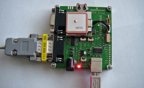
For a more permanent mounting of the EM406a, purchase the GPS Evaluation board from SparkFun Electronics. A very neat product though it does not provide access to the 1 PPS signal from the EM406a.
Q: What is the hardware connection between the AVR clock and the RS-232 interface on the computer?
A: You will need a cable consisting of a female DB-9 connector (for most PCs) and the 3-pin connector included with the clock. Wiring is as follows:
3-pin connector - 1:GND, 2:out/RXpc, 3:in/TXpc.
DB-9 connector - 5:GND, 2:RX, 3:TX.
Pin 1 of the 3-pin connector is next to the +(positive) pin of the Power Connector and is marked as ‘1’ on the connector itself.
Q: What baud rate do I set for the Serial interface to my computer (or some other terminal)?
A: The AVR clock uses a baud rate of 19,200. Other values are default (8 bits, 1 stop bit, no parity, and no handshaking)
Q: How do I communicate with the AVR clock using the Serial interface?
A: Once the cable between the AVR clock and the computer has been properly connected, you can use your favorite terminal program, such as HyperTerminal or Bray’s Terminal, and set it to use a 19,200 baud rate, 8 char, 1 stop, no parity, and no handshaking. Make sure you select the proper COM port, where the cable is plugged in, usually COM1. If the connection is good, the AVR clock will display a sign-on message when it starts. You can communicate by using the ‘x’ key. The AVR clock will show a command prompt with all available commands. Type 'h' for more details (see next item if this doesn't work.) All command keys can be either upper or lower case; the AVR clock will treat them as identical. Prompts will time out after 30 seconds.
Note that the Serial Command Line interface is not available when the GPS NMEA parsing option is enabled since that feature uses the serial port.
Q: Why is there no text when I request help using the 'h' command?
The online help text is now stored in the EEProm area since the Flash (program) area is completely full. This means that when you update the AVR Oscilloscope Clock from a previous firmware version, you will need to update the EEProm area too (file extension is .eep). This is optional and only required if you want to see the online help in the Serial Command Line interface. AVR Clocks originally shipped with V3.0 or later will have the EEProm area properly programmed. Resetting the EEProm area (new menu option) will NOT clear this help text.
Q: How do I send commands to the AVR clock using HyperTerminal?
A: HyperTerminal sends each character typed immediately to the AVR clock, which will prompt you for the next character, if needed. You can always type another ‘X’ to cancel a command. Please double check that hardware handshaking is turned off because it is the default in HyperTerminal.
Q: How do I send commands to the AVR clock using Bray’s Terminal?
A: Bray’s Terminal does not send each character typed immediately, as HyperTerminal does. You must select the white “send” line near the bottom of the window (transmit section) with the mouse and type the characters to send there. Do not add any CR or LF characters. Use the “send” button to transmit the characters, one at a time or all at once, whatever you prefer. The AVR Clock can buffer up to 128 characters at a time. For example to change the clock to 2PM, you can type “XT140000” in the send line and then hit the ->send button.
Bray’s Terminal also allows you to assign macros containing multiple characters. If you use those, you can send multiple commands in rapid succession. You’ll see that the AVR clock is incredibly responsive without affecting the display.
Q: My laptop does not provide an Serial interface. What can I do?
A: As of firmware Version 2.6, the use of the RS-232 interface is optional. However, it is used for firmware upgrades and still provides a very fast user interface. There are several USB to RS-232 converters available today. Unfortunately, I've been told of some problems using such a converter when doing a firmware upgrade. Make sure you use a high quality cable or a separate adapter like the "eval232r" unit from FTDI, which I tested myself, available at Mouser Electronics. SparkFun Electronics carries a "USB to RS232 Converter"
Q: If my oscilloscope is not near my computer, what should I do?
A: As of version 2.6, the use of the serial interface (which usually requires a computer) is optional. If you want to use the serial interface away from your oscilloscope, you can disconnect the AVR clock from the oscilloscope and check its operation near the computer independently (except for the Calibration Screen). The LED on the AVR clock will blink every second if it is operating properly. The AVR clock will also communicate its status through the RS-232 interface; you don’t need a hookup to an oscilloscope to change settings using the serial interface.
Q: What commands are available using the Serial interface?
A: Once the cable is connected properly, the clock will display a sign-on message on the terminal when it powers up. The command 'X' is used to get the clock's attention (interactive mode). A prompt will show:
Command(B,C,D,F,G,H,K,L,M,N,P,R,S,T,U,V):
B: Toggle Burn-in Prevention
C: Toggle Calibration Output
D: Set Date
F: Set Clock Face Mode
G: Toggle GPS NMEA input Parsing
H: Show extended Help
K: Toggle the Fractional Seconds Display
L: Toggle LED Blinking
M: Toggle 1PPS Trigger Mode
N: Set Numeric Display Mode
P: Set Clock Play Mode
R: Reset the EEProm Configuration Data
S: Show Status info
T: Set Time
U: Set Automatic Daylight Saving Time Adjustment
V: Toggle Verbose Output
Execution of any of these commands, or another 'X' will end the interactive mode. Prompts will time out after 30 seconds. Note that the commands can be given in either upper or lower case.
Q: How do I tell the AVR clock to change the Clock Face?
A: Use the 'F' command followed by a 2 digit numeric value.
The full list of options is:
00 12 hr dial
01 24 hr dial
(can show numbers 13..23 on the dial)
02 Roman Numerals
Dial
03 Binary Clock
Display
04 Minimal dial
Q: How do I tell the AVR clock to change the Numeric Display?
A: Use the 'N' command followed by a 2 digit numeric value.
The full list of options is:
00 12 hr
(AM-PM)
01 24 hr (International/Military
Time)
02 Hexadecimal
03 Date
04 No Numeric Field
Q: How do I tell the AVR clock to display just the dial on the analog clock?
A: Use the ‘F04’ command to select a dial with just 4 numbers. This mode is persistent.
Q: How do I tell the AVR clock to display the Numeric Display in AM/PM mode?
A: Use the ‘N00’ command to set the Numeric Display to AM/PM mode. This mode is persistent.
Q: How do I tell the AVR clock to start and stop blinking the LED?
A: Use the ‘L’ command to toggle the LED blinking. This will also suppress the 'G' notifications on the screen when a valid $GPRMC record has been received (in GPS mode). This mode is persistent.
Q: How do I tell the AVR clock to send the current time and date to the Serial interface every minute?
A: Use the ‘V’ command to toggle Verbose mode. This mode is persistent.
Q: How do I align the clock properly on my scope?
A: Select the Calibration Mode, command ‘C’, which will toggle between the regular clock and a Calibration Pattern on the scope, to adjust the display. While in Calibration Mode, use the Volts/Div VAR knobs together with the position knobs to get the best square possible; this screen can also be used to fine-tune the probe compensation adjustments.
Q: How do I set the time on the AVR clock using the Serial interface
A: Type ‘X’ on the terminal. Once you get a command prompt, type ‘T’. The AVR clock will prompt you for the time. The hours info must be entered in the 24-hour format. Here is the conversion from the US standard to 24-hour format:
|
US Regular Time |
24 Hour Time |
US Regular Time |
24 Hour Time |
|
12:00 a.m. |
00:00 |
12:00 p.m. |
12:00 |
|
1:00 a.m. |
01:00 |
1:00 p.m. |
13:00 |
|
2:00 a.m. |
02:00 |
2:00 p.m. |
14:00 |
|
3:00 a.m. |
03:00 |
3:00 p.m. |
15:00 |
|
4:00 a.m. |
04:00 |
4:00 p.m. |
16:00 |
|
5:00 a.m. |
05:00 |
5:00 p.m. |
17:00 |
|
6:00 a.m. |
06:00 |
6:00 p.m. |
18:00 |
|
7:00 a.m. |
07:00 |
7:00 p.m. |
19:00 |
|
8:00 a.m. |
08:00 |
8:00 p.m. |
20:00 |
|
9:00 a.m. |
09:00 |
9:00 p.m. |
21:00 |
|
10:00 a.m. |
10:00 |
10:00 p.m. |
22:00 |
|
11:00 a.m. |
11:00 |
11:00 p.m. |
23:00 |
You can also send the new time in one command, for example 'xt130000 will set the time to 1:00 PM
Q: How do I change the Clock Face to something more serene?
A: The AVR clock provides 3 different controls to change the clock face, providing a total of 30 different combinations. Use the ‘N’ command to select the Numeric Display mode (00-04). Use the ‘F’ command to select the Dial Display mode (00-04).
The combination of No Numeric Display and Minimal dial (XN04XF04) provides an serene display.
Q: How do I change the Triggering
method for the 1PPS signal?
A: The AVR triggers by default (when in a clean state) on the falling edge
of the 1PPS signal because the RTC, which is the default 1PPS signal generator,
produces a negative going signal. An external 1PPS signal may require a trigger
on the rising edge of the signal, for example if it is a long positive going
signal or the return to GND level is very slow. You can toggle the 1PPS trigger
mode using the 'M' command. The AVR Clock will reboot after this command since
the INT0 interrupt needs to be reinitialized.
Q: How do enter a User Name using the Serial Interface?
A: Use the 'W' command. You will be prompted for a the name and must type in 20 characters. Just add spaces to complete the 20 characters; trailing spaces will automatically be removed. Because of a bug in the software, the new name will not be saved if this is the first time a name is being changed. Please use the on-screen menu to change the User Name the first time (a 1 letter name will do), before using the 'W' command.
Q: Why is there is a flashing B on
my clock?
A: The RTC has reported a Low Battery. Please
power cycle the clock to check if it happens again. The next step is to test the
actual backup battery voltage with the power turned off. If it looks ok (2-3V),
you can clear the flag in the RTC by explicitly updating the time (long push or XT command)
and restarting the clock. If the battery voltage is too low (<1V), you’ll have
to change the Lithium backup battery. The original battery is a Renata CR1225FV,
Mouser part number 614-CR1225FV-LF; however, any 3V Lithium battery will work,
provided you connect it properly. This Battery warning also implies that the
clock time may no longer be accurate.
This warning can be caused by a short between the batteries + and - posts. This can happen if the small tabs on the side of the battery are not bent out, in which case that small tabs on each side may simultaneously touch the unused pad underneath the battery, causing a short, resulting in a Low Voltage State. Please make sure these unused tabs are bent out.
This warning will automatically stop after 60 seconds.
Q: Why does the AVR clock display a flashing letter P?
A: This happens when the AVR clock is in back-up mode, i.e., it does not receive the 1 PPS signal (1 Pulse per Second) from the RTC (or another external source). The AVR clock has a countdown timer that is activated after roughly 1 1/30 second (based on its own crystal oscillator), and it advances the time if no PPS signal was received.
This will most likely happen when a GPS device feeds the 1PPS signal and the device looses its satellite lock. The clock will keep going in that case, though running a little slow. If you have the NMEA output of the GPS device connected to the Serial Port (and the GPS option is selected with the proper local time zone offset), the AVR clock will automatically set the proper time and date once the GPS device gets another lock. A flashing letter "G" indicates the the time or date was changed based on the incoming NMEA records.
The RTC has its own backup battery and is always powered. To reset the RTC, please remove it from its socket and reinsert it (with the power disconnected, of course) The time and date will be random if this happens, so please Reset the EEProm configuration data or set the correct time and date immediately.
Q: Why does the AVR clock display a flashing letter G?
A: This happens when the AVR clock determines that its time and/or date is different from the time/date obtained from the NMEA output of a GPS device connected to the Serial Port (and the GPS option is selected with the proper local time zone offset). The AVR clock will update its time (and the on board Real Time Clock) to the time/date obtained from the GPS device and will display a flashing letter "G" for 5 seconds.
Q: Why are there 3 pins on the connector marked Ground?
A: These three pins are all three Ground. They are there to give you more freedom hooking up ground wires.
Q: The clock dial doesn't seem to be perfectly round. Is there a way to fix this?
A: Yes there is. What you are seeing is the result of non-linearity of the DAC. You can add a Load Resistor in the range 2.5K to 3.3K between the output terminal and the ground, for both channel 1 and channel 2. This is easiest done on the bottom side of the clock. Adding these resistors results in a loading down of the DAC outputs, reducing the voltage swing, thus reducing the non-linear behavior of the current switches inside the DAC. The resulting voltage swing is now in the range 0..1V (without these resistors it is 0..4V) and you'll need to set the VOLTS/DIV selector for both channels to 0.1V/DIV. A beneficial side effect of this modification is reduced vector retracing visibility (because the Output Impedance is reduced). Thanks to Joe Sousa for this investigative work.
Q: When using 1x probes (or BNC cables), I see Vector Retracing. Is there a way to fix this?
A: Please apply the Load Resistor modification listed above.
Q: How does the AVR clock trigger on the 1 PPS signal?
A: By default the AVR clock uses a 1PPS signal generated by the on-board RTC. This is a negative going pulse so the AVR clock triggers on the negative going edge. Most GPS units have a TIMEKEEP signal that is normally low and pulses high for 200 mSecs every second; by default, the AVR clock triggers on the negative edge at the end of this pulse. You can use the Serial Command 'M' to toggle the trigger mode of the AVR clock.
Please note the following. The AVR Clock has an internal pull-up resistor enabled on this pin so that the pin is HIGH when not connected (e.g., when the shunt is removed from JP6). If your 1 PPS signal is normally low, it will have to PULL DOWN the signal to LOW, and a small current will run from the AVR to your signal source.
Q: What is the purpose of the push button switch on the AVR clock?
A: It is the user input interface. A short push will enter the Menu mode. A long Push will enter the Change Mode. The button switch is also used to allow firmware upgrades using your PC (see boot loader).
Q: What is the purpose of the ‘Z’ pin on the AVR clock?
A: The Z (Intensity) output on the AVR clock dims the beam at the appropriate moments. This output will increase its voltage towards 5V to decrease the scope intensity (Tektronix 400 scopes convention). Please connect this signal to your oscilloscope intensity control input, if present. It is very effective in suppressing highlighted dots on the screen.
Q: What are the voltage levels present on the CH1 and CH2 terminals?
A: The voltage levels on the CH1 (X) and CH2 (Y) terminals range from 0 to 4 Volts, assuming a 5V power supply. This range can easily be reduced by adding two load resistors, as described above
Q: I’m seeing a pattern on my scope but no clock display. What is wrong?
A: Make sure your scope is in X-Y mode and that the proper Vertical Mode is selected. On many Tektronix scopes this is the CH2 Vertical Mode. Also double check the probe connections, as well as their Ground. The CH1 and CH2 terminals are very sensitive to any kind of noise. Just touch them with your fingers while the clock is running.
Q: I’m seeing an uneven line at the edge of the scope screen. What is wrong?
A: You have only one channel properly connected to the scope. Make sure both channels are properly connected to the AVR clock CH1 and CH2 terminals.
Q: My Tektronix 7000 series oscilloscope and its plug-ins have no X-Y mode. Can I still use it with the AVR clock?
A: Yes, but you will need two separate vertical plug-ins, one in the usual vertical slots on the left and one in one of the horizontal slots (on the right).
Q: The digits in the oscilloscope display look malformed. How can I fix this?
A: You need to adjust the probe compensation to correct this.
Q: How can I test the accuracy of the RTC?
A: In Calibration Mode, the RTC will output a 32,768 KHz square wave signal on the CLOCKOUT pin; please note that this is an Open Drain pin, so you’ll need to connect a 10K resister between the CLOCKCOUT pin and +5V to enable this signal. The crystal oscillator can be tuned by inserting a variable capacitor between OSCI (pin1) and GND. You can read more about the accuracy of the PCF8563 RTC in the application note referenced in the “Technical Information” section of the AVR oscilloscope website. See also the datasheet of the PCF8563 in the same location.
Q: Is the oscilloscope I use permanently dedicated to this clock?
A: No, the only connections are the 2 probes and possibly the Intensity Control. Just unhook the probes (and Intensity Control cable), and you can use your scope for its intended purpose.
Q: How do I update the firmware of my AVR Clock?
A: Please read this page.
Q: How do I know which firmware
version my clock is running?
A: As of firmware V2.6, the current firmware version is shown on the options
menu, top line. Enter the options menu using a short push (push and release) on
the button switch. If the clock reboots when using a short push, you are running
an older version (V2.4 or V2.5). Please update the firmware in that case.
Q: Where can I find the firmware for the AVR Oscilloscope Clock 3.0?
A: The firmware for version 3.0 is available on the main Oscilloscope Clock page, under "Technical Information", link "Flash Image V3.0 (Serial Download)". This firmware version is the clock application itself (excluding the boot loader) and can be downloaded to the clock using the serial cable. If you ever have a problem programming the AVR microprocessor and get stuck, don't hesitate the remove the chip from the clock board and send it to me for repair/replacement (Please read this page)
Q: I don't have the ability to update the firmware myself. What do I do?
A: Please read this page.
Q: Can I use my official AVR programmer (like the STK-500) to reprogram the AVR?
The flash memory on this ATmega168 AVR is configured into two areas, the clock application (word address 0x0000-0x1dff) and the boot-loader (word address 0x1e00-0x1fff). Using the boot-loader to reprogram the AVR will ONLY update the first area, which is all you need to get an updated clock version.
Programming the flash memory using this "clock only" firmware with an official AVR programmer, will reprogram all the flash memory, in effect clearing the boot-loader area. Turn off the "Boot Reset Vector Enabled" fuse and the clock will work just fine. However, you won't be able to update the firmware using the serial link anymore (you still can use the AVR programmer.) To maintain the ability to update the flash memory using the serial link, you will need a flash image of the combined "clock+boot loader", which is available on request.
You are advised to first save a copy of the entire Flash area and store this
copy in a safe place before updating to another application without a boot-loader.
This way you can restore the AVR Clock incl. the boot-loader later.
Q: My AVR fuses are set incorrectly. How should they be set?
A: First of all, be very careful because you may make the AVR inoperable by setting the wrong fuse, especially the “Use External Clock” fuse. Do NOT attempt to change any fuses by using the Avrprog program. This program is only used to download new firmware, nothing else. Finally, in the AVR world, UNPROGRAMMED fuses (i.e., disabled) have a ‘1’ value, whereas PROGRAMMED fuses (i.e., enabled) have a 0 value. It’s easy to get confused, depending on the program being used to modify the fuses. Here is a list of PROGRAMMED fuses for the Atmega168 AVR used in the scope clock:
|
Boot Flash section size=512 words | |
|
Boot Reset Vector Enabled | |
|
SPI (Serial Program downloading) enabled | |
|
Preserve EEPROM memory through the Chip Erase cycle | |
|
Brown-out detection level at VCC=2.7V | |
|
Ext. Crystal Osc; Frequency >= 8.00 MHz. 16K CK/14 CK + 65 ms. |
Programming an AVR microcontroller and setting the fuses need to be done using an AVR programmer. Popular models are the STK-500 compatible types or the AVR Dragon from Atmel (highly recommended for its in-circuit emulation support). Check out the Atmel or AVRfreaks websites for more information.
Q: Why does Avrprog show incorrect settings for the fuses (in the “Advanced” page)?
A: Avrprog 1.40 does not formally support the Atmega168 microcontroller yet, so the controller is identified as an Atmega16, close but not identical. This results in incorrect interpretation of the fuse data by Avrprog.
Q: This AVR clock is too serious.
Can’t it do anything fun?
A: Do you wish time was passing faster, or do
you want to go back in time? Try the Play Rev or Play FF menu options (or
use the P command (00-03)).
You’ll see the clock obeying your wishes! Try them together using Play FR!
Note that for either of these fun modes, the Real Time Clock (RTC)
will not be updated; once you exit the Play Mode, the clock will read the actual
time and date back from the RTC.
Q: Why does this AVR clock have so many options?
A: I used to work for Microsoft, where we tried to please everyone J.
Q: How do I show the capabilities of this AVR clock to my spouse?
A: Run the clock in DEMO mode. You can select this form the on-screen menu: Short Push to select the menu, advance to the Demo field by issuing Long Pushes, activate the Demo using a Short Push. The clock will enter demo mode. No user settings will be changed by the demo, nor will the time in the Real Time Clock be changed. At the end of the demo, the clock will automatically restart in normal operation mode.